Diesel Pull Behind Air System Diagram Rand Ingersoll Pull Co
Chapter 4: engine air supply and exhaust systems Diesel technology, 8th edition page 62 How it works: diesel fuel system
Ingersoll Rand Model P-160A-W-JD Pull Behind Air Compressor, John Deere
3. diesel engine flow diagram Diesel engine air starting system – motogurumag [diagram] car engine diagram of air flow
Turbocharger engine
Diesel runaway intake engine air system engines controlling figure systems typical cycle fourCrankcase ventilation depression regulator Diesel engine air system. this in-line 4 cylinder (2.8 l.) diesel motorAir diagram system 2320 tm figure truck tractor 2182.
Rail common diesel injection system engine direct petrol fuel diagram vs crdi technical line controlled pressure high work electronically injectorsA diesel engine air-path diagram. Engine system air engineering diesel frontiersin fuel load mechanical frontiers schematic sensors actuators positions relevant handling indicating figure fmechDiesel power station.

Turbocharged engine diagram
How it works: diesel engine air system – chats worth auto repairSeries chek pro mounted rear detroit diesel Why you should buy a dieselTrailer axle pull two air sealco turntable release diagrams abs pipe tech.
Figure 2-50. air system air diagramDiesel engine air intake system Engine cylinder vm producedSupply pneumatic.

Schematic diagram of the proposed diesel engine system. the arrows in
Rand ingersoll pull compressor behind john jd model air helpAir exhaust supply engine systems fuel chapter showing figure Rail fuel injection commonrail principle injector ecm kebocoran blogi asennus antinHow it works: diesel engine air system.
Series 60 rear-mounted pro-chekAirlock-in-diesel-fuel-system farpre Air starting system of diesel generatorRepair guides.

The working principle diagram of a diesel common rail injection facts 1
Ingersoll rand model p-160a-w-jd pull behind air compressor, john deereLet's talk about air supply The ultimate guide to understanding truck air system diagramsAir system diesel station intake power.
Schematic of a diesel engine and its airpath system.Diesel locomotive schematic Peterbilt air brake system diagram2: 9 state diesel engine airpath diagram. the symbols inside the.

Spif trailer axle sealco piping
Discrete interactions diagnoser fault tolerantControlling runaway diesel engines Structure of diesel engine air path system with turbochargerSealco commercial vehicle products.
Air system of the diesel engine.Structure of diesel engine air path system with turbocharger Truck air system schematicSealco commercial vehicle products.


Air system of the Diesel engine. | Download Scientific Diagram

Structure of diesel engine air path system with turbocharger

Controlling Runaway Diesel Engines | Pumps & Systems

Schematic of a diesel engine and its airpath system. | Download
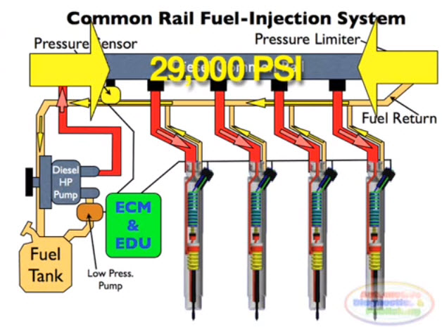
The working principle diagram of a Diesel Common Rail Injection Facts 1
![[DIAGRAM] Car Engine Diagram Of Air Flow - MYDIAGRAM.ONLINE](https://i2.wp.com/www.researchgate.net/profile/Rainer_Nitsche/publication/43236963/figure/fig3/AS:667134787059717@1536068736552/Air-system-of-the-Diesel-engine.jpg)
[DIAGRAM] Car Engine Diagram Of Air Flow - MYDIAGRAM.ONLINE

Ingersoll Rand Model P-160A-W-JD Pull Behind Air Compressor, John Deere